4-20mA to Modbus RS-485 enclosure
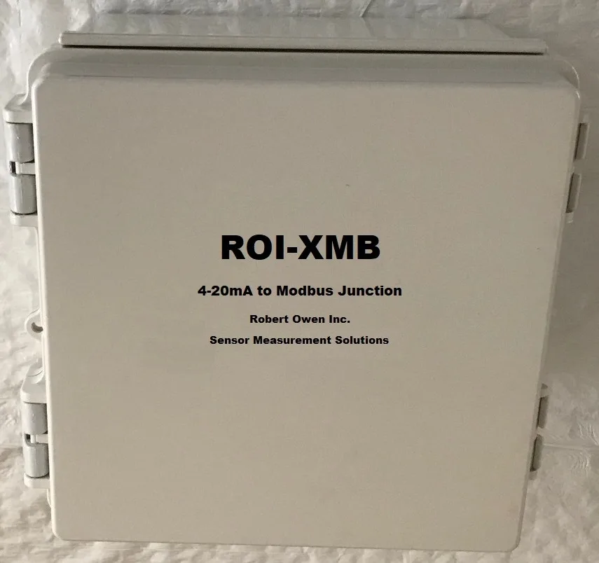
A ready-to-install enclosure that brings 4-20mA sensor transmitters onto Modbus RS-485. Power, terminals and an ROI-IOM module are mounted and wired inside, so you connect the transmitters, connect the RS-485 cable to your PC or PLC, and start monitoring. Also available wired for 0–30 V signals or dry contacts.
Formerly the ROI-XMB.
Transmitter monitoring without the panel build
The 4-20mA current loop carries most industrial sensor measurements: temperature, pressure, level, flow and humidity. Reading those loops on a PC usually means sourcing a power supply, an I/O module, terminals and an enclosure, then wiring it all together.
The ROI-IOM-420 arrives as one integrated subsystem in a hinged wall-mount enclosure. Readings update live and continuously, ready for lists, charts and logging in your monitoring software.
- Mounted in an enclosure with power and connectors
- Four 4-20mA inputs on the ROI-IOM, AI1 to AI4
- RS-485 connection to a desktop PC, laptop or PLC
- Windows and Linux compatible, with simple Modbus software available
Specifications, all versions
- Current inputs
- 4 (AI1–AI4), 0–25 mA, 120 Ω
- Voltage inputs
- 4 (AV1–AV4), 0–30 V
- Conversion
- 12-bit SAR ADC, 8.7 ENOB
- Analog output
- 1 (AO1), 0–10 V
- Digital inputs
- 6 (DI1–DI6), 0–40 V
- Relay outputs
- 4 (O1–O4), 6 A / 250 V AC
- Interface
- RS-485, 1200–115200 baud
- Power
- AC mains, 24 V DC supply inside
- Field wiring
- Screw-clamp terminals, 30–12 AWG
- Enclosure
- Hinged, wall mount
Choose a version
Every version uses the same ROI-IOM module, so specifications, software and Modbus communication are identical. The difference is the enclosure wiring: each enclosure version arrives with its inputs wired to terminals for one type of signal. The ROI-IOM on its own has uncommitted inputs, for wiring into your own panel.
| Part number | Inputs wired for | Module channels | Relay outputs O1–O4 | Typical use |
|---|---|---|---|---|
| ROI-IOM-420 | 4 × 4-20mA transmitters, loop powered | AI1–AI4 | Uncommitted | Pressure, level, flow and temperature transmitters |
| ROI-IOM-420-EM | 4 × 4-20mA transmitters, loop powered | AI1–AI4 | 24 V DC for SSR activation | Transmitter monitoring that switches external loads |
| ROI-IOM-030 | 4 × 0–30 V DC signals | AV1–AV4 | Uncommitted | Voltage-output sensors, 12 V and 24 V status signals |
| ROI-IOM-030-EM | 4 × 0–30 V DC signals | AV1–AV4 | 24 V DC for SSR activation | Voltage monitoring that switches external loads |
| ROI-IOM-4DC | 4 × dry contacts, wetting supplied | DI1–DI4 | Uncommitted | Door, float, flow and pump-run switches |
| ROI-IOM-4DC-EM | 4 × dry contacts, wetting supplied | DI1–DI4 | 24 V DC for SSR activation | Contact monitoring that switches external loads |
| ROI-IOM | Uncommitted: module only, all I/O available | All | Uncommitted | Panel builders and distributed RS-485 networks |
Standard enclosure versions
Relay outputs O1–O4 are uncommitted. They remain available on the module for you to wire to your own alarm, beacon or control circuit.
-EM versions
The relays are connected to the enclosure 24 V DC supply, so each relay output delivers 24 V DC to activate a solid-state relay. Wire the SSR input straight to the terminals, with no separate control supply to add.
Need a mix, such as two transmitters and two contacts? Ask for a custom wiring.
How it works
Read standard transmitter signals
Each of the four inputs accepts 0 to 25 mA, covering the standard 4-20mA span with room to detect under-range and over-range conditions such as a broken loop or a failed transmitter. Inputs have a 120 Ω impedance and are sampled by the ROI-IOM on-board 12-bit ADC at up to 500 kS/s. Keep transmitter cable runs within 15 m, the specified input cable length.
An integrated subsystem, ready to wire
Inside the hinged wall-mount enclosure: an ROI-IOM module, a 24 V DC power supply and screw-clamp terminal blocks. The enclosure runs from AC power. Each version wires one input group to the field terminals: AI1–AI4 on the ROI-IOM-420, AV1–AV4 on the ROI-IOM-030, and DI1–DI4 on the ROI-IOM-4DC. The relay outputs are uncommitted on standard versions, or on -EM versions connected to the 24 V DC supply to drive solid-state relays. The module’s other I/O remains available for custom wiring.
Live data on your PC
Connect the RS-485 port to a Windows or Linux desktop or laptop. Real-time readings update continuously, adding new values to lists, charts and logs. Robert Owen Windows data acquisition software is available separately, or read the enclosure from your own Modbus software or PLC.
Windows data acquisition software →Grow from four inputs to a distributed network
The enclosure can also act as the coordinator for a larger RS-485 network. Add ROI-IOM nodes along a daisy-chained bus of up to 1200 m, each reading four more transmitters, and connect the whole network to one PC. Paired with ROI-XMA thermistor transmitters, this builds a 32-channel temperature measurement system.
32-channel temperature measurement →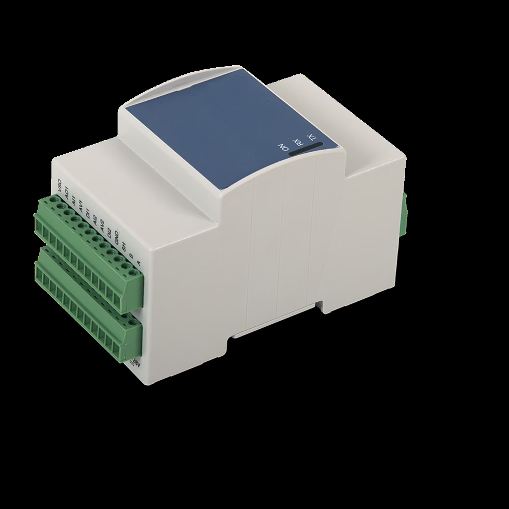
The ROI-IOM inside
Every version is built around the ROI-IOM Series DIN-rail module, which combines industrial measurement with embedded processing and RS-485 communications. On its own, the ROI-IOM has uncommitted inputs: all of the I/O below is available. In the enclosure versions, one input group is wired out to the field terminals.
| I/O | Channels | Range | Max cable |
|---|---|---|---|
| Analog current in | AI1–AI4 | 0–25 mA, 120 Ω | 15 m |
| Analog voltage in | AV1–AV4 | 0–30 V, >450 kΩ | 15 m |
| Analog out | AO1 | 0–10 V, 30 mA, ±2 % FS | 15 m |
| Digital in | DI1–DI4 | 0–40 V, 49 kΩ | 30 m |
| Digital in or 5 V logic I/O | DI5–DI6 | 0–40 V, 6.5 kΩ; or 5 V I/O | 30 m / 10 m |
| Relay out | O1–O4 | 6 A, 250 V AC | — |
| Supply out | VSO, 5VO | VS − 1 V, 300 mA; 5 V, 350 mA | — |
| Communications | RS-485 | Half duplex, 1200–115200 baud | — |
Custom embedded calculations are available as a service.
4-20mA monitoring with the ROI-IOM →From transmitter to PC
Everything between the field wiring and the RS-485 cable is already built and tested, so installation comes down to mounting the enclosure and landing the wires.
Three steps to monitor
- Mount and power: hang the enclosure and connect AC power.
- Wire the transmitters: land each 4-20mA loop on the input terminals.
- Connect and read: run RS-485 to the PC or PLC and start the Modbus software.
Related solutions
4-20mA sensor transmitter monitoring
Use the ROI-IOM on your own DIN rail to bring transmitters onto RS-485.
Learn more →Analog sensor signal conditioning
Convert thermistors and potentiometers into standard 4-20mA signals.
Learn more →Embedded interface conversion
Multiport and wireless RS-485 coordinators with on-edge processing.
Learn more →Need to monitor 4-20mA transmitters from a PC?
Tell us which transmitters you have, how many, and where the data needs to go. We will confirm the build and the wiring before it ships.