Sensor Signal Conditioning
Sensor signal conditioning turns a sensor’s raw signal – a changing resistance from a thermistor, RTD or potentiometer, or a transmitter’s current – into a standard signal that a PLC, a PC or a network can read. Robert Owen conditions sensors four ways: 4-20 mA to a PLC, USB to a PC, Modbus RS-485 for many points on one cable, and wireless when there is no cable at all.

Choose by where the reading goes
4-20 mA
To a PLC
Loop-powered transmitters for a spare analog input. Thermistor, RTD and potentiometer.
4-20 mA transmitters →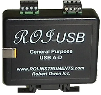
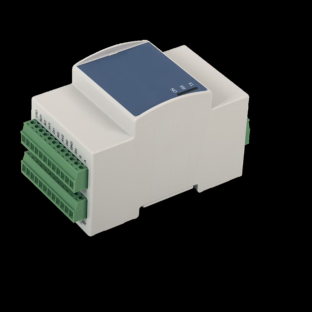 Modbus RS-485
Many points, one cable
Transmitters and ROI-IOM I/O on one RS-485 cable, from a few points to hundreds.
Modbus RS-485 → Wireless 2.4 GHz
No cable at all
Sensors read where they are, sent to a PC up to about a mile away.
Wireless →Choose by sensor
Find your sensor (left) and where the reading has to go (top). “To order” means built for your application – request a quote.
| Sensor or signal | 4-20 mA to a PLC | USB to a PC | Modbus RS-485 | Wireless |
|---|---|---|---|---|
| 10K NTC thermistor | Thermistor transmitters | ROI-USB | Multi-channel system | ROI-RFX-10K |
| RTD (PT1000 / Pt100) | RTD transmitters | To order | Via transmitters + ROI-IOM | To order |
| Potentiometer (position) | Potentiometer transmitters | To order | Via transmitters + ROI-IOM | To order |
| 4-20 mA transmitter | Already 4-20 mA | ROI-USB | ROI-IOM | ROI-RFX-MA |
| Switch contacts | — | To order | ROI-IOM digital inputs | To order |
Prices for every product: products and selection guide →
Why condition the signal
- Use what you have – a spare PLC input or a PC port, no special input card
- Accuracy – the sensor’s curve is linearised and scaled to engineering units
- Distance – 4-20 mA, RS-485 and wireless carry the reading far from the sensor
- Reliability – a 4-20 mA live zero shows a broken loop; isolation stops noise and ground loops
Noise, ground loops or high-voltage separation? The ROI-ISOV10 isolation amplifier conditions voltage signals with isolation.
Part of a complete solution
Signal conditioning is the first of three capabilities Robert Owen combines into working test, measurement and monitoring systems – from one sensor to hundreds.
- Conditioning – this page
- Signal processing
- Data acquisition and recording
Sensor signal conditioning – common questions
What is sensor signal conditioning?
Converting a sensor’s raw output – a resistance, a small voltage or a current – into a standard, scaled signal such as 4-20 mA, a digital reading over USB or Modbus RS-485, or a wireless message that a PLC or PC can read directly.
Which output should I choose?
A spare PLC analog input: 4-20 mA. Sensors near a PC: USB. Many points or long distances: Modbus RS-485. No way to run cable: wireless.
Can you condition a sensor or range that isn’t listed?
Yes. Other thermistor values, custom spans and other sensors are built to order – tell us the sensor, the range and what it connects to.
Do you supply the software too?
Yes. USB and wireless products include ROI viewing and recording software, and we build complete systems with software or PLC/SCADA integration.
Have a sensor to connect?
Tell us the sensor, the range and what it has to connect to – we’ll recommend the conditioning and the rest of the system.
Questions? Contact us – we look forward to answering them.