32-channel NTC thermistor temperature measurement
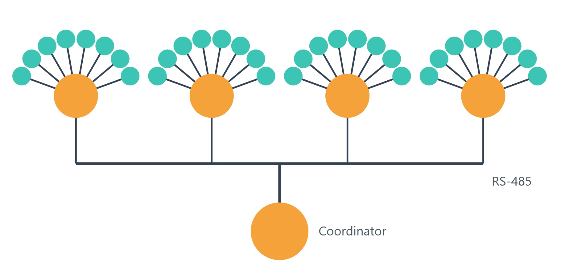
Measure temperature across a whole facility, not just around one logger. A 4-20mA transmitter sits at every thermistor, a DIN-rail node collects each group of four, and one RS-485 cable brings every reading back to your PC or controller.
Put the measurement at the sensor
A thermistor is a resistance, and resistance signals do not travel well. Long leads pick up noise and add error. This system converts each thermistor to a 4-20mA current right where it is mounted, so the signal leaving the sensor is already an industrial standard.
Groups of four transmitters wire into a nearby ROI-IOM node. The nodes share a single RS-485 bus, which carries the readings over long distances to the coordinator. Start with 4 channels and add nodes until you reach 32 or more.
- Standard 10K NTC thermistors read through PLC-compatible 4-20mA transmitters
- Four channels per node, on a 3-module DIN-rail ROI-IOM
- One RS-485 cable links every node, up to 1200 m per segment
- Relay outputs at every node for local over-temperature alarms
System at a glance
- Channels
- 32 (8 nodes × 4), expandable
- Sensor
- 10K NTC thermistor @ 25 °C
- Transmitter
- ROI-XMA, 4-20mA loop powered
- Node
- ROI-IOM, 4 current inputs, 4 relays
- Network
- RS-485, up to 1200 m per segment
- Coordinator
- ROI-XMB to a PC, or ROI-RFX-CPU embedded
How the system is built
Four layers, each doing one job, from the thermistor to your software.
Convert the thermistor where it is mounted
The ROI-XMA transmitter accepts a 10K NTC thermistor and outputs a loop-powered 4-20mA signal. It runs from 7.5 to 36 V DC, responds in 10 ms, and snaps onto 35 mm DIN rail or a surface-mount base. Mount it close to the thermistor so the resistive leads stay short. Choose the range that covers your process:
| Range | Sensor | Output | Details |
|---|---|---|---|
| −10 to 50 °C | 10K NTC | 4-20mA | View transmitter |
| 0 to 50 °C | 10K NTC | 4-20mA | View transmitter |
| −10 to 75 °C | 10K NTC | 4-20mA | View transmitter |
| 0 to 75 °C | 10K NTC | 4-20mA | View transmitter |
A two-wire current loop to the node
Each transmitter connects with two wires, in series with the supply and the measuring input. Because the signal is a current, not a voltage, cable resistance does not change the reading as long as the loop has enough supply voltage.
The ROI-IOM VSO terminal supplies the loop at the module supply voltage less 1 V, with up to 300 mA available, which is enough for all four loops. Each current input has a 120 Ω input impedance. Keep 4-20mA runs from transmitter to node within 15 m, the cable length specified for the ROI-IOM analog inputs. For longer loops, contact us about surge protection and loop isolation.
Collect four channels on the DIN rail
The ROI-IOM reads four 0-25 mA current inputs with a 12-bit SAR ADC at up to 500 kS/s. On a 60 °C transmitter range that works out to about 0.2 °C per step before averaging, and the high sample rate leaves plenty of room to average.
The same node adds four 6 A relays and six digital inputs, so an over-temperature alarm, fan or cooling pump can be switched right at the measurement point. Custom embedded calculations, such as scaling to °C or alarm logic, can be provided as a service.
Full ROI-IOM specifications →One cable links every node
The nodes share a half-duplex RS-485 bus running at 1200 to 115200 baud. A/B lines carry ±15 kV ESD and ±500 V surge protection. Use 9600 or 19200 baud on long runs, up to 1200 m per segment, and reserve 115200 baud for shorter buses.
Wire the bus as a daisy chain of shielded twisted pair, with a 120 Ω terminator at each physical end and short drops to each node. Each node needs local 11 to 30 V DC power. At 19200 baud, a full segment of 32 nodes refreshes in under a second, which is far faster than temperature changes.
Distances and limits
Plan each run against the limit for its layer. Contact us before exceeding any of them.
| Run | Signal | Practical limit | Notes |
|---|---|---|---|
| Thermistor to ROI-XMA | Resistance | Keep short | Mount the transmitter at the sensor. Lead resistance adds error. |
| ROI-XMA to ROI-IOM | 4-20mA | 15 m | ROI-IOM analog input cable specification. Longer runs on request. |
| ROI-IOM to coordinator | RS-485 | 1200 m per segment | 9600 or 19200 baud, terminated daisy chain, up to 32 nodes. |
| Beyond one segment | RS-485 or radio | By design | Repeaters, a multiport coordinator, or radio links. Contact us. |
Scale by adding nodes
Every node adds four channels. Nothing upstream changes.
| ROI-IOM nodes | Channels | Typical use |
|---|---|---|
| 1 node | 4 | One rack, one enclosure or one chiller |
| 2 nodes | 8 | Supply and return across several loops |
| 8 nodes | 32 | Rack row, plant room or test stand |
| 32 nodes | 128 | One full RS-485 segment |
Bus layouts
Daisy chain Recommended
One continuous cable runs from node to node, terminated at both ends. This is the layout RS-485 is designed for and the simplest to install and troubleshoot.
Star of chains By design
To cover areas spread in several directions, each direction gets its own properly terminated chain, joined at a multiport coordinator or RS-485 hub. A true star of single drops is not used, because unterminated branches cause signal reflections.
Choose a coordinator
The coordinator polls every node and hands the readings to your software.
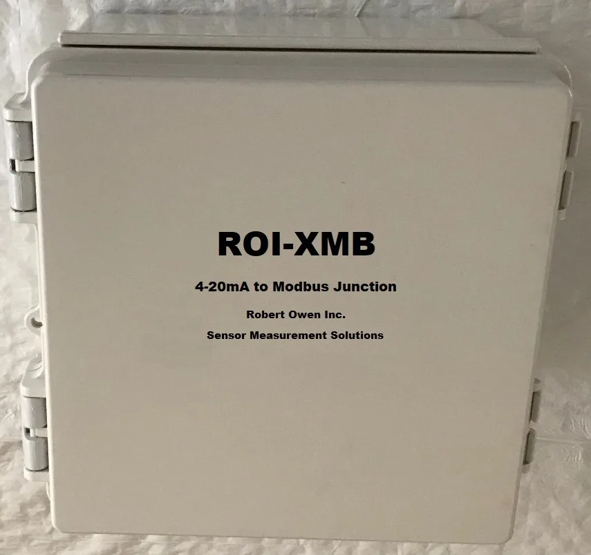
ROI-XMB: wired to a PC
A ready-to-wire enclosure with a 24 V DC supply and terminal blocks that connects the RS-485 bus to a Windows or Linux PC. Its own four 4-20mA inputs read at 15-bit resolution, so it also works as a higher-resolution node on the same bus.
ROI-XMB enclosure →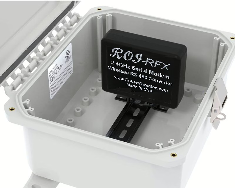
ROI-RFX-CPU: embedded and remote
A multiport RS-485 converter with on-edge data processing. Run a separate chain from each port, link distant clusters by private radio where cable is impractical, log to USB storage, and feed a remote status dashboard.
Embedded interface conversion →Where it is used
Any job with many temperature points spread over more distance than one logger can reach.
- Liquid-cooled computing and rack-level thermal mapping
- Computer room and data center monitoring
- HVAC, chillers and refrigeration systems
- Heat exchanger and cold-plate supply and return
- Electrical enclosure and power-system monitoring
- Dryers and industrial process monitoring
- Building and environmental monitoring
Plan your system in four steps
- Pick a range: choose the ROI-XMA range that covers each point.
- Group the sensors: four transmitters per ROI-IOM, within 15 m of the node.
- Chain the nodes: one RS-485 cable, up to 1200 m and 32 nodes per segment.
- Choose a coordinator: ROI-XMB for a PC, ROI-RFX-CPU for embedded or radio.
Related solutions
NTC thermistor transmitters
The ROI-XMA 10K NTC to 4-20mA transmitter, also usable on its own with any spare PLC analog input.
Analog signal conditioning →ROI-IOM Series
Complete power, analog, digital, relay, communications, environmental and mechanical specifications.
View complete specifications →Modbus RS-485 sensor monitoring
Connect 4-20mA and DC voltage sensors to PLC, controller and monitoring systems over RS-485.
Learn more →Planning a multi-point temperature system?
Tell us how many points, the temperature ranges, and how far apart they are. We will lay out the transmitters, nodes and coordinator and quote the complete system.