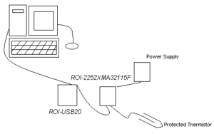
Example 4-20mA thermistor transmitter wiring diagram
A Simple 4-20mA Transmitter Operation Description
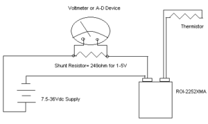
The 4-20mA transmitter can be looked at as a temperature controlled variable load. It is in series with the power supply and current measurement shunt resistance.
The effect is similar to the transmitter acting like a potentiometer. One that will vary total load resistance according to change in temperature. Varying total current in circuit to be measured as a voltage. The voltage change across the current shunt resistance is based on current change.
When the ROI-XMA Thermistor transmitter is wired, it is wired as a loop circuit. This needs with the correct DC power supply and current measurement device, You can see this in the following diagram.
Example 4-20mA thermistor transmitter wiring diagram
So when the ROI-XMA Thermistor transmitter is used with the ROI-USB current measurement A-D, the PC can be used to measure a Thermistor with higher precision than a direct measurement system.
The 4-20mA transmitter gain can be adjusted. This can minimize the span of the temperature sensor range. The result is a precise PC temperature recorder. A recorder with precision greater than a tenth of a degree.

Multiple transmitters can be connected to the same A-D. Brought together to form a multi channel Thermistor data acquisition system.
A PC and software are also required. This is in addition to the A-D, the 4-20mA temperature transmitters, and the Thermistors. These pieces all form a complete Thermistor data acquisition system.
So when the ROI-USB is used with Excel, a tremendous flexibility is added to the system. For example Excel can be used for real time display and analysis of data. Such as, values of temperature displayed in a chart. With updated data values linked to ROI-USB.
So you can use the link to learn more about the ROI-XMA series of transmitters.
Also you can use this link to learn more about the ROI-USB measurement systems.
