Digital inputs and relay outputs on RS-485
The ROI-IOM Series adds six digital inputs and four 6 A relays to a PLC, SCADA or monitoring system over one RS-485 connection. Read switches, contacts and logic signals, and switch pumps, fans, alarms and valves from the same DIN-rail module.
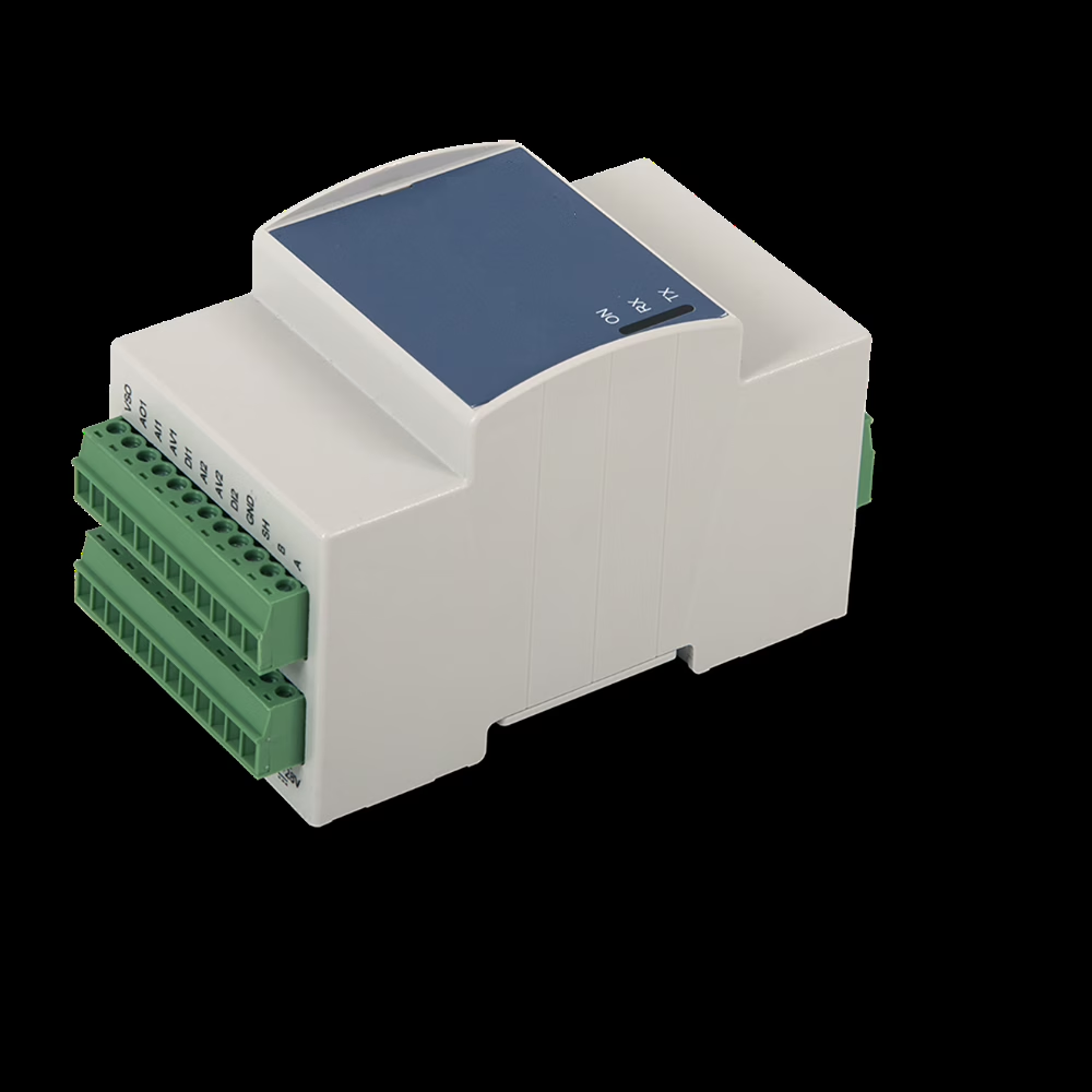
Contact monitoring and switching in one module
Many monitoring jobs come down to on/off signals: a door switch, a float switch, a pump run contact, an alarm output from another instrument. The ROI-IOM reads those signals on six digital inputs and drives four relays, so status monitoring and actuation share one module and one RS-485 cable.
- Six digital inputs — DI1–DI6, accepting 0 to 40 V
- Four relay outputs — O1–O4, 6 A at 250 V AC
- RS-485 half-duplex — 1200 to 115200 baud, with ±15 kV ESD protection on A/B
- Industrial build — −20 to +60 °C operation, 3-module DIN-rail housing
Digital I/O at a glance
- Inputs
- 6 (DI1–DI6), 0–40 V
- Relays
- 4 (O1–O4), 6 A / 250 V AC
- Interface
- RS-485 half-duplex
- Baud rate
- 1200–115200
- Supply
- 12–28 V DC nom. (11–30 V)
- Temperature
- −20…+60 °C
- Housing
- 3-module DIN rail, IP20
How the digital I/O works
Read voltage signals up to 40 V
All six inputs accept 0 to 40 V, so 12 V and 24 V control signals connect directly. DI1–DI4 switch high above 4.9 V and low below 3.4 V with a 49 kΩ input impedance, and can run on cables up to 30 meters. DI5–DI6 switch at 5.1 V and 3.4 V with a lower 6.5 kΩ input impedance and the same 30 meter cable limit.
Wire switches and contacts
A dry contact has no voltage of its own. The module’s VSO terminal supplies the operating voltage less 1 V at up to 300 mA, which is enough to wet a contact wired to any of DI1–DI4. DI5 and DI6 are also specified as 5 V logic I/O with a 10 kΩ pull-up to +5 V, where a contact switching the input to ground reads directly.
Switch real loads
Four relays rated 6 A at 250 V AC switch fans, pumps, heaters, beacons and contactor coils without an interposing relay. Resistive AC loads up to 1500 VA, inductive loads up to 250 VA and single-phase motors up to 185 W at 230 V AC are within rating. DC breaking capacity is 3 A at 30 V DC.
One cable to the control system
The RS-485 half-duplex port runs from 1200 to 115200 baud, with manual or automatic TX/RX management. The A/B lines carry ±15 kV ESD protection (human body model) and surge protection, which matters on long runs through a plant. Input states and relay commands pass between the module and a PLC, SCADA system or PC using Modbus RTU.
Digital I/O specifications
From the ROI-IOM Series technical specifications.
Digital inputs DI1–DI4
- Input range
- +0…+40 V
- Impedance
- 49 kΩ
- High threshold
- VIH 4.9 V
- Low threshold
- VIL 3.4 V
- Max cable
- 30 m
Digital inputs DI5–DI6
- Input range
- +0…+40 V
- Impedance
- 6.5 kΩ
- High threshold
- VIH 5.1 V
- Low threshold
- VIL 3.4 V
- Max cable
- 30 m
DI5–DI6 as 5 V logic I/O
- Output low
- VOL 0.1 V
- Output high
- VOH 5.0 V
- Input high
- VIH 1.4 V
- Input low
- VIL 1.1 V
- Pull-up
- 10 kΩ to +5 V
- Max cable
- 10 m
Relay outputs O1–O4
| Parameter | Specification |
|---|---|
| Rated current | 6 A |
| Rated voltage | 250 V AC |
| Rated load (AC1, resistive) | 1500 VA |
| Rated load (AC15, cos φ = 0.5) | 250 VA |
| Single-phase motor (230 V AC) | 185 W |
| Breaking capacity (DC1) | 3 A @ 30 V DC · 0.35 A @ 110 V DC · 0.2 A @ 220 V DC |
| Electrical life (AC1, rated load) | 50,000 cycles |
| Mechanical life | 20,000,000 cycles |
| Operate / release time | 6 / 4 ms |
| Dielectric strength (open contacts) | 1000 V AC |
| Dielectric strength (coil to contacts) | 4000 V AC, basic insulation |
| Relay terminals | 5.08 mm pitch, up to 3.3 mm² (12 AWG) |
From field contact to control system
The ROI-IOM sits on the DIN rail next to the equipment it watches. Field wiring stays short, and a single RS-485 pair carries every input state and relay command back to the controller.
Where a decision needs to happen at the module rather than in the PLC, custom embedded calculations can be provided as a service.
Three steps to connect
- Wire the I/O — contacts and signals to DI1–DI6, loads to relays O1–O4.
- Connect RS-485 — A/B to the bus, and set the baud rate to match the controller.
- Read and switch — the PLC or SCADA system reads input states and commands the relays.
Related solutions
ROI-IOM Series
Complete power, analog, digital, relay, communications, environmental and mechanical specifications.
View complete specifications →Modbus RS-485 voltage input
Use the same module’s four analog voltage inputs to bring DC signals onto the RS-485 bus.
Learn more →0-5VDC signal conditioner monitoring
Monitor conditioned sensor outputs alongside your contacts and relays on one DIN-rail platform.
Learn more →Need to monitor contacts or switch loads over RS-485?
Tell us what you need to read, what you need to switch and which controller it connects to. We will confirm the wiring and the configuration before it ships.